
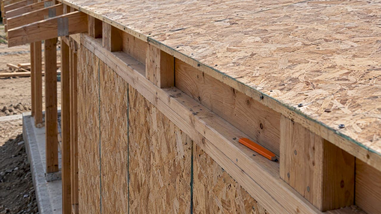
A roof diaphragm connection is the set of fasteners, framing members and metal connectors that move lateral force from the roof sheathing into the shear walls below. If one link in that chain is missing or undersized, the wall capacity you calculated never gets used. This guide walks through the load path link by link, explains where chords and collectors fit, and gives you a checklist for design and plan review on 1-story and 2-story wood buildings.
TL;DR
- A roof diaphragm collects lateral wind or seismic force and delivers it to shear walls. The connection is where that delivery happens.
- The load path runs from sheathing nails, to boundary framing (rim joist or blocking), to a connector at the wall top plate, to the shear wall.
- Chords resist the tension and compression from diaphragm bending. Collectors carry force along the edge to the walls that resist it.
- Diaphragm capacity depends on panel thickness, fastener size and spacing, and penetration depth. Blocked diaphragms carry more than unblocked ones.
- Check every connection on the plans, from sheathing edge to wall line, before you send the set to review.
Table of Contents
- What a roof diaphragm connection is
- The load path, link by link
- Chords and collectors
- Nailing, blocking and diaphragm capacity
- Common roof-to-wall connection methods
- Our perspective
- How connection forces and requirements are determined
- California, Oregon and Nevada: what to confirm
- Checks during design review and inspection
- Where the work is easiest to organize
- FAQ
- Sources
What a roof diaphragm connection is
A roof diaphragm is a horizontal or sloped structural unit, usually the roof system, that collects lateral seismic or wind forces and distributes them to the vertical lateral-force-resisting system, such as shear walls. In light wood framing, the diaphragm is the roof sheathing nailed to rafters or trusses. It acts like a deep, thin beam lying on its side, with the shear walls as its supports.
The connection is everything that joins that "beam" to its supports. According to the Applied Technology Council, connections between diaphragms and shear walls transfer shear primarily through fasteners (nails or staples) that attach the sheathing to boundary members, and through mechanical connectors that attach those members to the walls.
Two things make this detail worth your attention:
- It is a series system. The force passes through every element in turn, so the weakest one governs.
- It is easy to leave undefined. Sheathing nailing gets a schedule. The transfer from boundary framing to the wall often gets a vague note.
For the wider picture of how roofs, floors and walls share lateral force, see our guide to wood framing lateral systems.
The load path, link by link
The ATC describes the load path at a roof-to-wall connection as sheathing fasteners, boundary edge framing such as a rim joist or blocking, and an attachment to the shear-wall top plate, such as sheet metal angles and nails. Follow it in order:
- Lateral load enters the roof. Wind pushes on the building envelope, or seismic mass in the roof and upper walls accelerates. Either way, the roof sheathing receives the force.
- Sheathing fasteners move shear across the panel. Shear flows through the nails along panel edges and into the framing.
- Boundary framing collects the force. A rim board, blocking or the end of a truss or rafter takes the shear at the edge of the diaphragm.
- A connector crosses the gap to the wall. Framing clips, angles, or toe-nails and nailed blocking transfer the shear into the top plate.
- The top plate delivers it to the wall sheathing. From there the shear wall takes over, and hold-downs and anchors carry overturning and sliding to the foundation.
Write the unit shear in plf at each step. When the number at the connector is higher than the number at the sheathing edge, you have found a detail that needs more fasteners or a different connector.
The elements in one table
| Link | What it does | What to define on the plans |
|---|---|---|
| Sheathing nailing | Transfers shear from panel to framing | Panel grade and thickness, nail size, edge and field spacing |
| Blocking | Supports unsupported panel edges and delivers shear | Location, size, nailing to the panel and to the plate |
| Boundary member (rim, blocking line) | Collects shear at the diaphragm edge | Member size, splice details |
| Wall-top connector | Moves shear into the top plate | Connector type, fastener count, spacing in plf |
| Chord | Resists diaphragm bending tension and compression | Member, splices, continuity |
| Collector (drag strut) | Carries force along an edge to a wall | Force, member, connections at each end |
| Shear wall top plate and below | Delivers force down the wall | Plate splices, wall nailing, hold-downs |
Chords and collectors
Chords and collectors are often confused, and both belong in your connection checks.
Chords are members along the diaphragm boundaries that resist tension and compression forces induced by the diaphragm's bending action, much like the flanges of a deep beam. In a typical wood roof, the top plates or boundary framing serve as chords. The splices need to carry the force, not just the member.
The ATC notes that chords must be designed for both tension and compression, because these forces reverse during seismic events. A splice detail that works only in tension is incomplete.
Collectors work differently. The ATC explains that forces are transferred through diaphragm boundary connections, where collectors carry forces along the edge to shear walls or frames. You need a collector when a shear wall is shorter than the diaphragm edge it serves, which happens often with openings, garage fronts and offset wall lines.
For a full walk-through of chord checks, see our roof diaphragm chord design article and the structural guide on diaphragm chords in lateral design.
Nailing, blocking and diaphragm capacity
The sheathing nailing sets the shear capacity that the connection must match. APA states that diaphragm shear capacity depends on panel thickness, fastener size and spacing, and depth of penetration. Change any of these and the capacity changes with it.
Blocking also matters. APA's guidance is that blocked diaphragms, where all panel edges are supported and connected, carry significantly more load than unblocked ones. On a residential roof you may find that blocking only the high-shear zones near the walls is enough, while the middle of the roof stays unblocked. Mark those zones on the roof framing plan so the framer and the inspector see the same thing.
There is a practical upside to using the roof as a diaphragm. APA explains that wood structural panel diaphragms are efficient because they use existing roof and wall sheathing, often eliminating the need for expensive additional bracing. That efficiency only holds if the nailing and connections are built as drawn.
To set up the schedule itself, read nailing schedules in shear design. For panel options, see types of engineered wood shear panels.

Common roof-to-wall connection methods
The construction tech notes from the masonry industry list the common ways roofs connect to walls: direct bearing, pocket, ledger and hanger connections, chosen according to wall type and structural requirements. That source addresses masonry walls. On wood-framed residential projects, the same ideas appear as:
- Bearing on the top plate. Trusses or rafters sit on the double top plate and are tied with framing clips or hurricane ties. Shear transfer happens through blocking or clips between the members.
- Ledger and hanger connections. Used where a roof framing member meets a wall from the side, such as a lower roof tying into a taller wall. The ledger fasteners carry both vertical and lateral loads.
- Blocking between trusses or rafters. Solid blocks sit over the wall, nailed to the top plate with angles or toe-nails, and sheathing is nailed to the blocks.
Whichever method you pick, state the shear capacity of the connector in plf, not just its product name. A clip rated for uplift may carry little lateral shear along the wall, and the reverse is also true.
Our perspective
Most roof diaphragm problems we see at review are not calculation errors. They are coordination gaps. The sheathing schedule says one thing, the wall line table says another, and the connector between them is a general note.
On 1-story and 2-story wood buildings, the fix is to keep the diaphragm, the wall lines and the connection forces in one organized set. When you see the unit shear on each wall line, the collector forces at openings, and the hold-down and strap demands in the same place, the connector schedule almost writes itself.
That is why we built ShearWise Pro around residential wood framing rather than general-purpose structural modeling. Our approach is designed to organize wall lines, openings, full-height segments, roof information, transfer straps and story drift checks, then produce a clean PDF that a reviewer can follow without a phone call.
A focused tool does not replace engineering judgment. It gives you more time to apply it, because the bookkeeping is already done.
Evalin
How connection forces and requirements are determined
The steps below are the order most engineers follow. Check the result against the code and standards adopted where the project sits.
- Establish the lateral loads. Wind and seismic forces for the roof level. Our overview of lateral loads in wood structures covers the inputs.
- Compute the diaphragm shear along each wall line. Use tributary width or rigid-diaphragm distribution, depending on the roof and the code provisions you apply. Our roof diaphragm design worked example goes through the numbers.
- Select sheathing and nailing. Match the panel, nail size and spacing to the highest unit shear, and decide where blocking is required.
- Size the chords and collectors. Find tension and compression at each boundary and check splices.
- Select the wall-top connectors. Divide the unit shear by the connector capacity to get spacing, and show it in plf or inches on center.
- Check the wall below. Confirm shear wall nailing, hold-downs, transfer straps and drift. See our wood frame building lateral analysis guide for the whole sequence.
Where wind uplift is part of the load, the continuous load path also runs vertically. In U.S. hurricane-prone regions, guidance from the Building America Solution Center says a licensed structural engineer is typically required to determine the connections that resist and transmit wind uplift and lateral shear. Even outside those regions, treat uplift and lateral shear as one continuous chain.
California, Oregon and Nevada: what to confirm
These three states each adopt and amend model codes on their own schedules, and local jurisdictions add their own requirements. Federal housing guidance on roof connections points the same direction: refer to local building codes and recognized standards for reinforcement and anchorage.
Before you finalize a connection detail on a project in Bakersfield, Portland, Reno or anywhere else in the region, confirm these items with the building department:
- The code edition currently enforced in that jurisdiction, including local amendments.
- Whether the department has standard details or checklists for diaphragm-to-wall connections.
- Whether the plan checker expects shear transfer, collectors and drag forces called out on the framing plan or only in calculations.
- Seismic and wind design parameters for the site, since they differ widely inside each state.
Putting these on the project checklist early saves a correction cycle.
Checks during design review and inspection
The CMHA tech note makes a point that applies to all materials: connections linking diaphragms to walls or frames are critical to structural integrity. Use this list at three stages.
Before the set leaves your office
- Every wall line that receives roof shear has a stated connector or nailing from the roof to the top plate.
- Blocking locations match the sheathing zones in the schedule.
- Collectors are drawn, sized and connected at both ends wherever walls are shorter than the diaphragm edge.
- Chord splices are shown and work in both tension and compression.
- The unit shear on the roof plan matches the unit shear on the wall line table.
At framing inspection
- Panel grade and thickness match the plans.
- Nail size and spacing match at panel edges, including at blocking and at boundaries.
- Connectors are the specified model, with every hole filled with the specified fastener.
- Blocking is installed where drawn, and the ends of collectors and chords are connected.
When a field change comes in
- A substituted truss layout or a moved wall changes the tributary width. Recheck the unit shear.
- A new opening can shorten a shear wall and create a collector. Recheck the wall line.
- Any change to nailing or connectors goes back to the engineer of record.
Where the work is easiest to organize
The connection forces come from the same numbers that drive shear walls: wall lines, openings, full-height segments, roof geometry and story drift. When those live in separate spreadsheets, a late change to one wall line can leave the connector schedule out of date.
ShearWise Pro keeps the wall line data, hold-down forces, transfer straps and roof information together and exports a PDF report built for review coordination. It is made for engineers, architects, designers, drafters, contractors and builders working on 1-story and 2-story wood-framed residential projects. You can try it free with three watermarked reports through the sign-up page. After the trial, Professional Monthly is $29 per month and Professional Annual is $250 per year, both listed on the plans page. If you want to see how the calculations are checked, browse the validation library.

For more on what the software covers, see shear wall software for residential wood buildings. For a broader view of the components in the system, read our guide to wood building lateral system components and the article on cutting hold-downs in shear wall design.
FAQ
What does roof diaphragm mean?
A roof diaphragm is the roof system acting as a horizontal or sloped structural unit. It collects lateral wind or seismic force and passes it to the shear walls or frames below. In wood buildings, it is the roof sheathing nailed to the framing.
What is a roof diaphragm connection?
It is the chain of sheathing nails, boundary framing, connectors and top plate attachments that transfers shear from the roof to a wall. Each element must carry the same unit shear, so the weakest element governs the design.
What is the difference between a chord and a collector?
A chord resists the tension and compression caused by the diaphragm bending, and it runs along the diaphragm boundary. A collector carries force along an edge to a shear wall or frame that is shorter than the edge. Both need sized members and connections, and both can govern near openings.
Does blocking matter for a roof diaphragm?
Yes. A blocked diaphragm, where all panel edges are supported and connected, carries significantly more load than an unblocked one. Many residential roofs need blocking only in the high-shear zones near the walls, so mark those zones on the framing plan.
Who determines the connection requirements?
The engineer of record sets them, using the loads and the code adopted by the local jurisdiction. In hurricane-prone U.S. regions, a licensed structural engineer is typically required for the continuous load path. Confirm local amendments with the building department before finalizing details.
Sources
- Diaphragm (structural system), Wikipedia
- Seismic Response of Wood-Frame Construction, Applied Technology Council
- Building Safety and Earthquakes, Applied Technology Council
- Shear Walls & Diaphragms, APA
- Diaphragms and Shear Walls Design and Construction Guide, APA
- Floor and Roof Connections to Masonry Walls, CMHA TEK 05-07A
- Continuous Load Path Provided with Connections from the Roof through the Wall to the Foundation, Building America Solution Center
- Roof Connections, HUD USER