
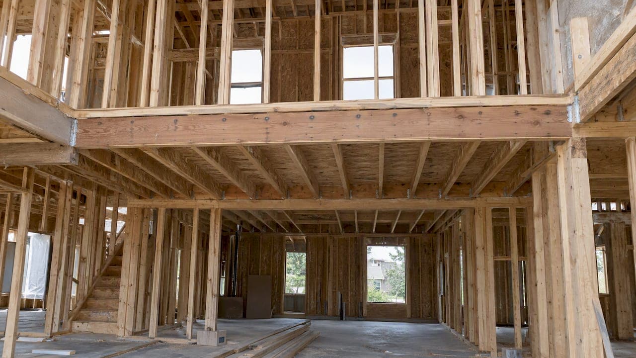
In a two-story wood building, lateral load travels from the roof and floor diaphragms into second-story shear walls, then first-story shear walls, then the foundation. Diaphragms, collectors, hold-downs, straps or continuous rods, rim-joist blocking and anchor bolts keep that path unbroken. Where walls offset or openings interrupt the line, collectors or transfer diaphragms restore continuity.
TL;DR:
- Check story shear Fx separately from diaphragm force Fpx; combining them can underdesign floors, while wall force sharing depends on relative stiffness.
- Size first story wall end anchors for cumulative overturning, R = R2 + R1, not that story's load alone; base forces can reach 40 kips ultimate under some conditions.
- Match floor transfer details to framing direction: perpendicular joists need blocking and toenails, while parallel framing can use a continuous rim joist.
- At offsets or interrupted diaphragms, collectors must remain continuous across interruptions, and transfer diaphragms can route forces to main chords.
- Use straps or designed plates at every top plate discontinuity; sheathing cannot splice the plates, and each splice must resist combined chord tension and compression.
Table of Contents
- How does the lateral load path work in a two-story building?
- What happens between the first and second story?
- Which connections carry uplift and shear between stories?
- What breaks the load path, and how do you restore it?
- Which design checks do you run, and what does the worked example show?
- What should you verify on drawings and at the jobsite?
- Why do simple load paths survive review?
- Organize your two-story shear wall calculations with ShearWise Pro
- FAQ
- Sources
How does the lateral load path work in a two-story building?
The load path must be continuous: roof, floor diaphragm, second-story shear wall, first-story shear wall, foundation. Each element has one job, and a gap at any link defeats the others.
- Diaphragms collect inertial lateral forces and distribute them to vertical elements. They must be interconnected with connections that provide stiffness, and they can behave as flexible or relatively rigid depending on relative stiffness.
- Shear wall stacks give the clearest path. Vertical continuity means each upper wall segment sits over a lower one, so shear passes straight down without a detour through the floor system.
- Chords and boundary elements carry the tension and compression that bending of the diaphragm or wall creates, and they must stay continuous across discontinuities.
- Foundation anchorage, meaning anchor bolts and plate washers, must develop uplift and overturning into the concrete.
For background on where these forces come from, see our guide to lateral loads in wood structures. Chord behavior is covered in more depth in diaphragm chords in lateral design.
What happens between the first and second story?
Redistribution begins with story shear. The vertical elements are checked for the story force Fx, while diaphragms are checked separately for their own design force Fpx. Treating the two as one number is a common source of under-designed floors.
- Overturning accumulates. The second-story wall delivers uplift at its ends, and the first-story wall adds its own. For a two-story perforated shear wall, anchorage at the base is sized for the cumulative force, R = R2 + R1, as shown in the AWC perforated shearwall design guide.
- Stiffness governs sharing. When several walls sit in one line, they need equal deflection or distribution by relative stiffness. A stiff short wall attracts more force than its length suggests.
- Collectors fill the gaps. When walls do not stack or the diaphragm is discontinuous, collectors must remain continuous across interrupting elements to deliver diaphragm shear to the walls below.
For the broader analysis sequence, see our wood frame lateral analysis guide.
Which connections carry uplift and shear between stories?
Hardware choices decide whether the calculated path exists on the jobsite. Uplift at the foundation can be severe: in some conditions, base-level overturning anchorage forces can reach upwards of 40 kips ultimate.
- Hold-downs at wall ends resist the tension from overturning and tie each story to the one below.
- Metal strapping transfers uplift across the floor zone, which suits cases where the floor framing blocks a straight vertical element.
- Continuous rod systems run through multiple stories. Detailing guidance from WoodWorks lists both strap and rod systems as common hardware and stresses careful anchor or embed detailing.
- Rim-joist or blocking transfer moves shear across the floor line. Where floor framing runs perpendicular to the wall, use blocking and toenails; where it runs parallel, a continuous rim joist can do the work.
- Mechanical top-plate splices keep chords continuous. Sheathing must not be used to splice top plates; use straps or plates designed for the net tension and compression.
Pro Tip: Top plates often act as both chord and collector, so design each splice for the combined force, not for chord tension alone.
For rod-specific guidance, read our hold-down rods in multi-story wood buildings guide.

What breaks the load path, and how do you restore it?
Offsets, re-entrant corners and large openings are the usual culprits. They concentrate chord forces at the corner, can induce torsion, and may turn part of a diaphragm into a cantilever.
- Use collectors deliberately. A collector, or drag strut, gathers diaphragm force and feeds it to a wall. Keep each one short, continuous across interruptions and tied well into the resisting element.
- Prefer transfer diaphragms where offsets are unavoidable. Routing collector forces to the main chords simplifies the path and shortens collectors.
- Avoid offset chords and stack walls wherever the plan allows, as practical diaphragm guidance recommends.
- Switch systems when needed. If shear walls cannot be arranged without long, heavily loaded collectors, consider braced frames or moment frames for that line.
- Settle the layout early. Discontinuities removed in schematic design cost nothing; removed during permit review, they cost a redesign.
Which design checks do you run, and what does the worked example show?
Run these checks in order:
- Vertical-element forces (Fx) for each wall line and story.
- Diaphragm design forces (Fpx) and the resulting diaphragm shear.
- Uplift accumulation and anchor sizing at each wall end.
- Chord tension and compression, including splice forces.
- Story drift against the governing limit.
The AWC perforated shear wall examples apply this sequence to a two-story wall and compare two detailing options. Configuration A uses a continuous rim joist sized to resist the induced forces. Configuration B uses blocking and metal strapping, suited to floor framing that runs perpendicular to the wall.
In both, the base anchorage carries R = R2 + R1, so the lower-story hold-down must include loads from above. Fastening is distributed across the full-height sheathed sections, and anchor bolts and plate washers are sized for the cumulative uplift, not the first-story value alone. The choice between A and B is a detailing decision. The load path and the accumulated forces stay the same. Our diaphragm shear transfer checklist walks through the Vd checks in more detail.
What should you verify on drawings and at the jobsite?
- Walls stack vertically, or collectors and transfer diaphragms are documented where they offset.
- Hold-down and anchor callouts appear on the plans, sized for accumulated uplift, with plate washers and adequate edge distances.
- Mechanical splices are shown at every top-plate discontinuity, with fastener schedules for sheathing and rim-joist attachment.
- Chord and collector lines are clear of MEP penetrations, and trade sequencing does not cut through them.
- Floor-to-wall transfer details match the framing direction actually built.
Why do simple load paths survive review?
In my experience, the drawings that clear permitting quickly show a load path a reviewer can trace in one pass. Complex collectors invite field substitutions and comment cycles. Bring structural, architectural and MEP into one early conversation so nobody discovers a discontinuity after framing starts. Detailing is as much a safety item as analysis: a correct calculation with an unbuildable connection protects no one.
— Evalin
Organize your two-story shear wall calculations with ShearWise Pro
We built ShearWise Pro as an online shear wall calculator for 1- and 2-story wood buildings. It handles wall lines, openings, hold-down forces, transfer straps and story drift checks, and exports clean PDF reports for review. Start with our free Three-Report Trial on the ShearWise Pro plans page, or browse worked calculation examples.

FAQ
What is the load path in a two-story wood building?
The path runs from the roof diaphragm through the floor diaphragm, second-story shear walls and first-story shear walls to the foundation. Each link must be connected, or the path is no longer continuous.
Why do first-story hold-downs carry more load?
They resist their own overturning plus the uplift delivered from the story above. The perforated shear wall example expresses this as R = R2 + R1.
When do you need a collector?
Use one when walls do not stack or the diaphragm is interrupted. It gathers diaphragm force and must stay continuous across interrupting elements.
Can sheathing splice a top plate?
No. Mechanical splices such as straps or plates, designed for the net tension and compression, are required at discontinuities.
Sources
- Calbo
- Perforated Shearwall Design
- 4.5 Procedures for Diaphragms
- Detailing and Best Practices of Developing the Lateral Load Paths