
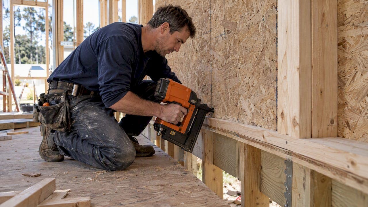
Sill nailing is the connection that moves shear out of the wall sheathing and into whatever sits below: a slab or stem wall through the sill plate and anchor bolts, or a floor frame through the bottom plate and its nails. The sheathing nails fasten the panel to the plate. Anchor bolts, or nails into the rim or blocking, then carry that force out of the plate. If either link is under-designed, the wall schedule on the plans does not matter, because the shear never reaches the foundation.
This guide covers what to check on 1-story and 2-story wood buildings: how the load path works, which nails and plate sizes the sources support, where penetration limits trap you, and how to document it all so a plan reviewer does not send it back.
TL;DR
- Sill nailing is only one part of the load path. Panel-edge nails, the plate, anchor bolts or floor nailing, and hold-downs all have to carry the same unit shear.
- A 2x bottom plate is common and efficient to frame. A 3x plate is needed only where the code conditions call for it, such as tight panel-edge nailing that risks splitting.
- In Seismic Design Category D, E or F, plates resisting more than 350 plf (ASD) or 490 plf (LRFD) need 3x nominal thickness, unless you use a 2x plate with double the bolts and plate washers.
- Standard 16d nails often cannot reach full penetration through a plate and floor sheathing into a rim joist. Check penetration, then reduce capacity or change the connector.
- Put the sill connection on the shear wall schedule and in the report, so the reviewer sees the same numbers you used.
Table of Contents
- What sill nailing has to do
- Two conditions: sill on foundation, bottom plate on framing
- Nail size, spacing and the schedule
- 2x or 3x sill plates
- Plate washers on anchor bolts
- Nail penetration: the trap at rim joists
- Field checks that avoid callbacks
- Where the sill connection fits in the full calculation
- Our view on sill nailing
- Document it with a shear wall calculator
- FAQ
- Sources
What sill nailing has to do
A shear wall is a system, not a pile of parts. APA describes the shear wall as a single unit that ties the floor, roof, wall and foundation together, with nailing, panel layout and anchorage working together. Designers aim for a continuous load path from roof and floors down to the foundation.
Sill nailing sits at the bottom of that path. Follow the force:
- Lateral load from wind or seismic enters the diaphragm and moves into the top of the wall.
- The sheathing carries it down as unit shear, in pounds per foot, through the panel-edge nails.
- The bottom edge nails transfer it to the sill or bottom plate.
- The plate passes it to the foundation through anchor bolts, or to the framing below through nails, blocking or straps.
- Hold-downs resist the overturning at wall ends.
The weak step governs. A wall with 3 in. edge nailing at the sheathing may still be limited by bolt spacing at the plate. That is why the bottom connection deserves its own line in the calculation, not a note saying "see typical detail."
Two conditions: sill on foundation, bottom plate on framing
The phrase "sill nailing" covers two different details, and mixing them up causes most of the confusion.
Sill plate on a concrete foundation
Here the sheathing nails go into the sill plate, and the anchor bolts take the shear from the plate into the concrete. The nails do not do the transfer to the foundation. Bolt size, spacing, edge distance, embedment and plate washers do. Our guide to shear wall anchor bolt layout walks through that side of the connection.
Bottom plate on a wood floor
On the second story, or a first story over a raised floor, the bottom plate sits on subfloor over a rim joist or blocking. Now nails carry the shear: from the plate through the sheathing into the framing below. The 2021 IBC fastener table separates the bottom plate to joist, rim joist, band joist or blocking connection into two rows. One row is for plates not at braced wall panels, with 16d common nails at 16 in. o.c. face nailed. A second row covers plates at braced wall panels and calls for a heavier nailing pattern. That prescriptive row is a floor for braced wall panels. An engineered shear wall at higher unit shear usually needs more, and the calculation should show how much.
Nail size, spacing and the schedule
The panel-edge nailing on your shear wall schedule sets the unit shear capacity of the wall. The sill connection must match or exceed it. A schedule should state the fastener type, length, gage and head size, plus a full sheathing specification. UpCodes' reproduction of the shear wall schedule requirement lists these items, including the capacity in pounds per foot.
Practical points when you set the schedule:
- Match nail type everywhere. If the schedule says 10d common and the framers use 8d box because it is in the gun, capacity changes. Name the nail on the plans.
- Edge spacing drives plate size. Closer spacing, such as 3 in. o.c. at panel edges, raises the risk of splitting the plate. This is the main reason 3x plates show up.
- Stagger where panels abut on one member. When two panel edges land on the same member, nails from each panel compete for space.
- Keep the nails set correctly. Overdriven nails reduce capacity. Our post for inspectors on the 3/8 inch edge setback in shear wall nailing covers what to verify in the field.
For a fuller look at how schedules are built and when to tighten spacing instead of adding studs, see nailing schedules in shear design.
A quick worked check
Suppose a wall line carries 380 plf (ASD) in Seismic Design Category D. Panel-edge nailing can meet that on the sheathing side. Now check the plate:
- 380 plf is above the 350 plf ASD threshold for a 2x sill in SDC D, E or F, so a 3x nominal sill is required, or the 2x alternative with extra bolts and plate washers.
- If you choose the 2x alternative, double the bolts you computed, and add 3/16 in. by 2 in. by 2 in. plate washers.
- Compare the framing consequences (see below) before settling. The better answer depends on bolt count, field labor and the nailing at the plate.
This is the kind of comparison that is slow by hand across many wall lines. It is also where a calculator that holds the wall line, shear and plate checks in one place saves time.
2x or 3x sill plates
The rule people remember is "always 3x for shear walls." The sources do not support that.
In Seismic Design Category D, E or F, the IBC requires 3-inch nominal sills where the plate resists more than 350 plf (ASD) or 490 plf (LRFD). Two-inch nominal plates are permitted if you double the required bolts and use steel plate washers of at least 3/16 in. by 2 in. by 2 in. below that threshold the 3x requirement does not apply from this provision.
The practical explanation, from a structural practice write-up, is that 3x members mainly prevent face splitting where adjoining panel edges put tight, staggered nailing into the same plate. A plate that receives the nailing of only one panel does not usually see those splitting conditions under the 2015 and 2018 SDPWS and IBC provisions the article cites.
The same source lists what 3x plates cost in the field:
- Framers cannot end-nail studs through the plate and must toenail instead.
- Precut studs need trimming by 1 in., which invites ordering errors and delays.
- Designers often prefer 2x plates with alternative anchorage unless loads require the larger member.
| Factor | 2x plate with extra bolts and washers | 3x plate |
|---|---|---|
| Stud attachment | Standard end-nailing | Toenailing required |
| Precut studs | Work as ordered | Trim 1 in. |
| Bolts | Doubled over the base requirement | Base requirement |
| Splitting risk at tight edge nailing | Managed by washers and spacing | Reduced by thicker member |
| Best fit | Moderate shear, field speed matters | High shear, adjoining panel edges on one plate |
Neither is automatically better. Run both on the wall lines that exceed the threshold, then choose by cost and detail simplicity.
Plate washers on anchor bolts
Anchor bolt washers are where local interpretation matters. Clark County, Nevada, published a sill anchorage interpretation dated July 2025 (marked as a final draft). It explains that prescriptive provisions for braced wall lines call for 0.229 in. by 3 in. by 3 in. steel plate washers between the sill plate and the nut. It also draws a line: a sealed engineered design may justify standard cut washers at non-braced wall lines, while prescriptive conventional construction requires the larger plate washers.
Two takeaways for work in Nevada, California and Oregon:
- Know which path you are on. Prescriptive plans need the prescribed washers. Engineered plans can justify alternatives, but you must show the reasoning.
- Call the building department when in doubt. Interpretations differ by jurisdiction and change. Check the current handout from the department that will review your plans, whether that is a county in Nevada, a Los Angeles County office, or the city or county where your project sits. We did not verify Bakersfield or Oregon jurisdiction handouts for this article, so confirm locally.
Whatever the path, state the washer size on the plans and in your calculation notes.
Nail penetration: the trap at rim joists

This is the detail that catches careful designers. A nail only reaches full design capacity if it penetrates the main member far enough. A WoodWorks presentation on shear wall connections explains that under the 2018 NDS a 16d common nail (0.162 in. diameter) needs a penetration of 10D, or 1.62 in., into the main member. Less penetration means a reduction: the ratio of actual to required penetration. For 1.25 in., that ratio is 0.77.
Now look at the stack-up for a plate on a floor:
- 1-1/2 in. plate
- 3/4 in. floor sheathing
- 3-1/2 in. nail length
The same presentation notes that this leaves too little nail in the rim joist to meet the 10D rule. Engineers handle it in two ways: apply the penetration reduction to the nail capacity, or change the connector. Flat straps such as an A35 can transfer shear without relying on nail length. If you reduce nails, your required nail count goes up, and the plate may not have room for them. Check that before you issue the plan.
What to put on the plans
- The nail type and size at the plate-to-framing connection
- Spacing, or number of nails per foot
- Any penetration reduction you applied
- The alternate connector, if used, and where
Field checks that avoid callbacks
Inspectors and framers see the same recurring problems at the sill. A short checklist helps both sides:
- Plate size matches the plans (2x or 3x, and washers where required).
- Anchor bolts are present at the spacing shown, with correct edge distance.
- Bottom-edge sheathing nails are the specified type, spaced as scheduled, and not overdriven.
- Where plates sit on framing, nails reach the member below and the count matches the plans.
- Hold-downs and straps are installed where the wall calculation placed them.
Design errors tend to repeat from job to job. Our list of common shear wall design mistakes is a useful pre-submittal read.
Where the sill connection fits in the full calculation
Sill nailing is one input among several. A complete 1- or 2-story wood calculation moves through:
- Wall lines and openings. Define each line, its length, and openings that break it into segments.
- Full-height segments. Compute unit shear on the segments that count, whether you use segmented or perforated methods. A 24 ft worked example of perforated shear wall design shows the method end to end.
- Schedule selection. Pick the sheathing and nailing that meet the unit shear. See the 770 plf shear wall schedule checklist for how that reads on permit plans.
- Sill and bottom connection. Check plate size, anchors, nails and washers against the same unit shear.
- Overturning. Size hold-downs and check deflection. The 0.20 in rule for holdowns and the 0.92 footnote in SDPWS matter here.
- Transfer. Add straps where force must pass across floors or openings.
If you want fewer hold-downs, wood shear wall design choices such as wall layout and sheathing strategy can reduce the count.
Our view on sill nailing
We built ShearWise Pro for residential 1- and 2-story wood buildings, so we see the same pattern in projects: the sheathing nailing gets all the attention, and the sill gets a typical detail. Then a reviewer asks how the 380 plf at that wall line gets into the slab, and the answer sits in three different places.
Our position is simple. Treat the sill connection as a calculated item, not a note. Show the unit shear, the plate size you chose and why, the anchor bolt or nail demand, and any washer or penetration adjustment, next to each other. When the load path is visible on one page, reviewers have less to question, and you have less to defend.
We also believe in choosing the simplest detail that works. If a 2x plate with extra bolts keeps framers on their standard stud lengths and end-nailing, that is often a better field outcome than a 3x plate. But only the numbers decide, and they should be on the report.
— Evalin
Document it with a shear wall calculator
ShearWise Pro organizes wall lines, openings, full-height segments, hold-down forces, transfer straps, roof information and story drift checks for 1- and 2-story wood buildings, and exports clean PDF reports for review coordination. You can see how it works in our shear wall software for residential wood buildings overview, or watch the training videos.
The free trial includes three watermarked reports at $0. After that, Professional Monthly is $29 per month and Professional Annual is $250 per year. Run one of your own projects through it and see whether the PDF answers your reviewer's questions.
FAQ
Does the sill nailing or the anchor bolt transfer shear to the foundation?
The anchor bolts do. Sheathing nails fasten the panel to the sill plate, and the bolts carry that shear from the plate into the concrete. Where a bottom plate sits on a wood floor instead, nails through the plate and subfloor into the framing below do the transfer.
When does a shear wall need a 3x sill plate?
In Seismic Design Category D, E or F, sill plates resisting more than 350 plf (ASD) or 490 plf (LRFD) need 3-inch nominal thickness. A 2x plate is allowed if you double the required bolts and add 3/16 in. by 2 in. by 2 in. plate washers. Tight, staggered panel-edge nailing is the usual splitting concern behind the rule.
What size nail is used for shear wall sill connections?
It depends on the wall's schedule and the connection. The prescriptive IBC fastener table uses 16d common nails for bottom plate to framing connections. Engineered walls follow the nail type, length and spacing on the shear wall schedule, which must be stated on the plans.
Why do 16d nails sometimes fall short at a rim joist?
A 16d common nail needs 10D, or 1.62 in., of penetration into the main member for full capacity. Through a 1-1/2 in. plate and 3/4 in. sheathing, a 3-1/2 in. nail leaves less than that in the rim. Reduce the nail capacity by the penetration ratio or use a flat strap.
Sources
- Practical Considerations for Shear Wall Connections and Details, WoodWorks
- Sill Plate Size and Anchorage in Seismic Design Category D, UpCodes
- Sill anchorage interpretation, Clark County, Nevada
- Shear Wall Plates, MODE architecture
- Earthquake Guide: Shear Walls, APA
- 2021 IBC 2304.10.2 Fastener requirements
- Shear Wall Schedule, Notes and Details, UpCodes