
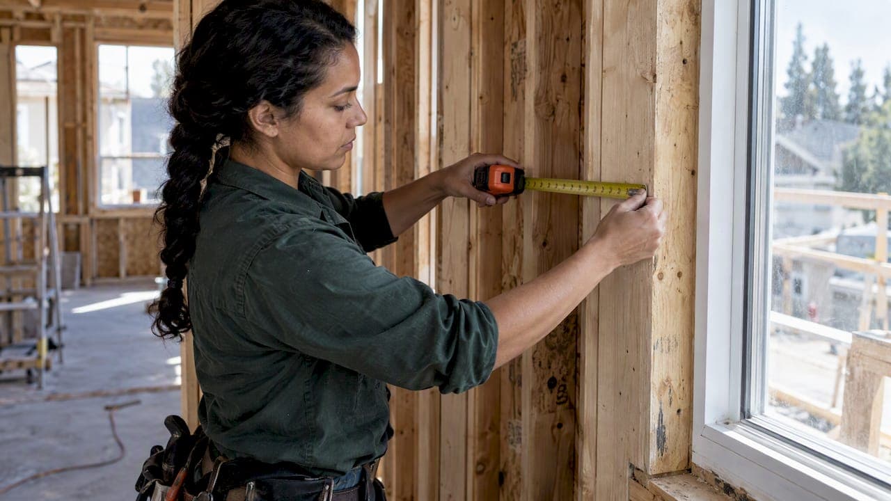
A shear wall pier is the full-height piece of wall beside an opening, and its design comes down to three things: its height-to-width ratio, the shear it carries, and the overturning force you must anchor at its edges. In wood-frame buildings you choose between the segmented and perforated methods, and that choice decides where hold-downs go and how much each pier is allowed to carry. This guide walks through both methods for 1- and 2-story wood buildings, then covers the concrete pier limits you may meet on a plan check.
TL;DR
- A pier is the wall segment beside an opening, equal in height to the shortest adjacent opening. The wall above or below an opening is a spandrel, not a pier.
- The segmented method counts only full-height sheathed segments and needs hold-downs at each segment edge. The perforated method treats the wall as one unit, uses hold-downs at wall ends and reduces capacity with an adjustment factor.
- Check aspect ratio, unit shear, overturning, and drift for every pier, then document the load path to the foundation or story below.
- Concrete piers follow ACI 318 rules, with a separate shear cap for individual piers. Confirm which code edition your jurisdiction enforces before you start.
Table of Contents
- What a shear wall pier is
- Choose the method first: segmented or perforated
- Step-by-step pier design for a wood wall line
- Openings and layout decisions that make piers easier
- A worked comparison: one wall, two methods
- Concrete piers: what changes
- Code editions in California, Oregon and Nevada
- Our perspective on pier design for low-rise wood
- Run your pier checks in ShearWise Pro
- Pier design checklist before you submit
- FAQ
- Sources
What a shear wall pier is
Openings break a shear wall into parts. The vertical parts beside doors and windows are piers. The horizontal parts above and below openings are spandrels. NIST's seismic design guide describes the same split: vertical segments are bounded horizontally by two openings or by an opening and a wall edge, and horizontal segments are bounded vertically in the same way.
The code definition adds height. A shear wall pier is the portion of a wall segment adjacent to and equal in height to the shortest opening on either side. That height matters because it sets the pier's aspect ratio, which limits how much shear it can resist.
In practice, on a residential wood plan:
- A narrow strip of wall between a window and a door is a pier only as tall as the shorter of the two openings.
- A corner section next to a garage door opening is a pier at the wall end.
- The header and wall below a window are spandrel-type elements. They help tie the wall together but do not count as full-height shear segments in the segmented method.
Choose the method first: segmented or perforated
Everything downstream depends on this choice, so make it before you size anything.
| Item | Segmented method | Perforated method |
|---|---|---|
| What resists lateral force | Only full-height sheathed segments | The wall as a whole, with reduced capacity for openings |
| Hold-downs | At each segment edge | At the wall ends |
| Opening effect | Openings separate the wall into independent piers | A shear-capacity adjustment factor accounts for openings |
| Typical use | Walls with few, wide full-height segments, or where hold-downs are acceptable at each pier | Long walls with regular openings where you want fewer hold-downs |
The segmented method assumes only full-height sheathing segments resist lateral forces and calls for hold-downs at each segment edge, while the perforated method puts hold-downs at the wall ends. The perforated method uses a shear-capacity adjustment factor and can eliminate hold-downs around openings. A technical bulletin on shear walls with openings summarizes the same difference.
The tradeoff is simple. Segmented design is easier to follow and check, but it can leave you with six hold-downs on a wall where a perforated layout needs two. Perforated design saves hardware but has stricter geometry conditions, so not every wall qualifies. Our article on reducing hold-downs from six to two shows how that plays out on a real wall line, and the 24 ft perforated worked example takes you through the numbers.
Step-by-step pier design for a wood wall line
Work one wall line at a time. For each line, follow this sequence.

1. Collect the wall line geometry
List the wall length, the wall height, every opening with its width and height, and the full-height segments between them. Record the pier width and the governing opening height for each. Mistakes here carry through every later check, so confirm dimensions against the current plans, not an earlier sketch.
2. Establish the lateral force on the line
Distribute the story shear to wall lines using your diaphragm assumptions and tributary roof and floor information. On a 2-story building, the lower line also picks up the load from the story above. Use the load combinations and the seismic or wind design values your jurisdiction requires. Wind and seismic often govern different walls in the same building, so run both.
3. Check the aspect ratio of each pier
Pier height divided by pier width limits the allowed shear. Narrow piers are penalized or excluded. For U.S. wood shear walls, we cover the 3.5:1 ceiling and the 2:1 adjustment in detail in our aspect ratio guide. A pier that fails the maximum ratio does not count toward resisting lateral load, so the remaining piers must carry the line.
4. Compute unit shear and compare with capacity
Divide the force assigned to the segment or line by the length of qualifying wall to get unit shear in pounds per foot. Compare it with the allowable or design capacity of your sheathing, nailing and, if used, blocking. Whether the panel edges are blocked changes the capacity noticeably, which is why we wrote up blocked vs. unblocked shear walls.
Interior gypsum can add to the capacity in some cases. AWC's wind design examples note that interior gypsum may be used additively with exterior wood structural panels for wind design when installed with the assumed nail spacings. Seismic design has more conditions, so read our gypsum board shear wall checklist before counting it.
5. Apply the opening adjustment (perforated only)
For a perforated wall, the adjustment factor depends on the ratio of opening area to wall area and on the maximum opening height. Apply it to the unit shear capacity, then confirm the wall's total capacity exceeds the line demand. Also confirm that the geometry conditions for the method are met, including those that govern the wall ends and any openings near them.
6. Compute overturning and size hold-downs
Overturning at the end of a pier is roughly unit shear times wall height, less the resisting dead load. In the segmented method, do this at each segment edge. In the perforated method, do it at wall ends, and add collector or strap forces where the load path requires them. AWC notes that WFCM tabulated hold-down capacities can be calculated by multiplying the ASD unit shear capacity of the reference shear wall by wall height.
Keep wind uplift separate. WFCM distinguishes overturning from lateral loads from uplift that arises solely from roof wind uplift, so do not net one against the other without checking the code's treatment.
7. Check hold-down deflection and story drift
Hold-down slip and anchor elongation add to wall rotation and drift. Our guide to the 0.20 in rule for hold-downs walks through the SDPWS steps. Then compare story drift with the code limit, particularly on 2-story buildings where lower wall deflection is amplified at the roof.
8. Document the load path
Reviewers want to see where each force goes: roof to top plate, top plate to wall, wall to hold-down, hold-down to foundation or the wall below. On the second floor, transfer straps or continuous rods carry forces through the floor system. Our two-story shear wall worked example covers a 20-foot wall with those transfers.
Openings and layout decisions that make piers easier
A pier problem is often a layout problem. Before you calculate, look at whether small changes remove the issue.
- Align openings vertically. Stacked windows and doors let piers line up between stories, so overturning carries straight down.
- Keep a full-height segment at each wall end. It anchors the line and gives a perforated wall the end segments it needs.
- Avoid very narrow piers. A pier that fails the aspect ratio limit contributes nothing, so widening it by a few inches can be cheaper than a stronger wall elsewhere.
- Group openings. Fewer, larger openings in a regular pattern are easier to analyze. NIST makes the same point for concrete walls: openings disrupt force flow and are best placed in regular patterns that give predictable force transfers.
- Treat the area below windows with care. Our window opening shear design steps show how to handle sill walls and the full-height segments beside them.
For segments next to openings, see also our full-height segment design guide.
A worked comparison: one wall, two methods
Take an exterior wall 24 feet long and 9 feet tall with two 4-foot windows and a 3-foot door, each opening 6 feet 8 inches or less in height. The numbers below are illustrative, not a code design.
- Segmented: the piers between and beside openings must each pass aspect ratio and carry their share of the story shear. Each pier needs hold-downs at both edges. With four piers, that can mean six or eight hold-downs on one line.
- Perforated: the wall acts as a unit. You compute the opening-area ratio, apply the adjustment factor to unit shear capacity, check that the wall-end segments qualify, and put hold-downs at the two ends only.
The perforated route usually costs more in capacity (the factor reduces it) and less in hardware. If the reduced capacity still exceeds demand, you gain a simpler wall. If it does not, upgrade nailing or sheathing, or return to the segmented method and add a pier. A calculator that runs both on the same geometry lets you compare them in minutes instead of rebuilding a spreadsheet.
Concrete piers: what changes
Most of our readers work in wood, but plan checks on mixed-use or podium projects sometimes bring concrete walls into the same set. The logic is similar, with different limits.
A 2026 Los Angeles County concrete shear wall plan review document states the following:
- Design forces come from LRFD combinations under the local code and ASCE 7 §2.3, and walls follow the applicable ACI 318 provisions.
- Walls under combined flexure and axial load are designed under ACI 318 §22.4 with the effect of openings considered, and flanged-wall effective widths and special boundary element requirements must be checked.
- Individual wall-pier nominal shear strength is limited to 10√f'c Acv, while the entire wall is limited to 8√f'c Acv, with the applicable strength reduction factor.
That last point is the key difference from wood: concrete piers get their own cap, separate from the whole wall. Also remember that for concrete, plastic hinge locations should be predicted so that failure does not occur in spandrel beams and walls, a point an academic study on coupled walls makes about openings and coupling.
If you model concrete walls in general finite element software, label each pier separately. Identical labels make the software combine their design forces, which hides the demand on any single pier.
Code editions in California, Oregon and Nevada
The edition your reviewer enforces sets your design values, so check it before you start. As of January 2024, the ICC adoption chart listed the 2021 IBC for California and Oregon, and for Nevada it showed that one or more state or local jurisdictions had adopted an edition without naming one. Adoption changes on a cycle, and local amendments are common, so confirm the current edition and amendments with the building department in your city or county, whether that is a Bakersfield permit counter or a Las Vegas plan check, before you submit.
For wood, the practical effect is which SDPWS edition is referenced, and whether your jurisdiction has additional limits on perforated walls or on gypsum in lateral systems. For anything your reviewer asks about, a clean calculation with the geometry, factors and load path laid out saves a correction cycle.
Our perspective on pier design for low-rise wood
We see the same pattern on residential projects. Engineers rarely get stuck on the equations. They lose time re-entering wall geometry, redrawing opening lists when the architect moves a window, and reformatting results for the reviewer.
That is why we built ShearWise Pro around the work of a 1- or 2-story wood building, not around general-purpose structural analysis. A wall line, its openings, its full-height segments, its hold-downs and transfer straps, roof information and story drift all sit in one project. When a window moves six inches, you change one number and see which piers and hold-downs it affects. Then you export a PDF a plan reviewer can read without asking for the missing pieces.
Our view on method choice is simple: run both the segmented and perforated options whenever the wall qualifies, and let the hardware count and capacity margin decide. Do not default to one method out of habit.
— Evalin
Run your pier checks in ShearWise Pro
ShearWise Pro is an online shear wall calculator and report platform for 1- and 2-story wood-framed buildings. You enter wall lines, openings and full-height segments, then work through hold-down forces, transfer straps, roof information and story drift checks, and export a PDF report for permit and review coordination. See how it fits residential work on our shear wall software page, or check the validation library for calculation examples.

Pricing is published on the plans page:
- Three-Report Trial: $0 for three watermarked reports.
- Professional Monthly: $29 per month.
- Professional Annual: $250 per year.
Start with the trial on a real project and compare the output with your current process. Sign up to try ShearWise Pro.
Pier design checklist before you submit
- Pier and opening dimensions match the current architectural plans.
- Method chosen and its geometry conditions confirmed.
- Every pier passes the aspect ratio limit, or is excluded from the capacity.
- Unit shear is below capacity for the sheathing, nailing and blocking shown.
- Opening adjustment factor applied if the wall is perforated.
- Hold-downs sized at segment edges or wall ends, with wind uplift handled separately.
- Hold-down deflection and story drift checked.
- Load path shown from roof to foundation, including straps on the second floor.
- Code edition and local amendments confirmed with the building department.
For more worked examples, browse the ShearWise Pro blog.
FAQ
What is the difference between a pier and a spandrel?
A pier is the vertical wall segment beside an opening, equal in height to the shortest adjacent opening. A spandrel is the horizontal wall portion between openings above and below, or between openings stacked vertically. Research on coupled walls uses the same terms. In wood design, piers act as shear segments while spandrels mostly tie the wall together.
Do I need a hold-down at every pier?
Only with the segmented method, which places hold-downs at each segment edge. The perforated method puts them at the wall ends, subject to its geometry conditions and the capacity reduction for openings. Check the code edition your jurisdiction enforces before relying on either.
Can a narrow pier count toward shear resistance?
Only if it passes the aspect ratio limit in the governing standard. Piers beyond the limit are excluded, and those within a reduced range get a capacity adjustment. See our aspect ratio guide for the 3.5:1 ceiling and 2:1 adjustment.
Are concrete pier checks the same as wood?
No. Concrete follows ACI 318, and individual piers have their own nominal shear limit of 10√f'c Acv, separate from the 8√f'c Acv limit for the whole wall, as stated in the 2026 Los Angeles County review document. Wood piers rely on sheathing, nailing and hold-down checks.
Which code edition applies in my city?
It depends on your jurisdiction's adoption and amendments. California and Oregon listed the 2021 IBC as of January 2024, and Nevada adoption varies by jurisdiction. Confirm with your local building department before you design.
Sources
- NIST GCR 11-917-11, Seismic Design of Cast-in-Place Concrete Special Structural Walls
- Shearwall Pier, UpCodes
- Analytical solution for a two-layer transversely isotropic wall study
- Segmented and Perforated Shear Walls course
- SIPA Technical Bulletin No. 12, Design of SIP Shear Walls with Openings
- AWC, Wood Shear Wall Design Examples for Wind
- Los Angeles County, Concrete Shear Wall Plan Review
- ICC Master I-Code Adoption Chart
- ETABS modeling of pier and spandrel elements