
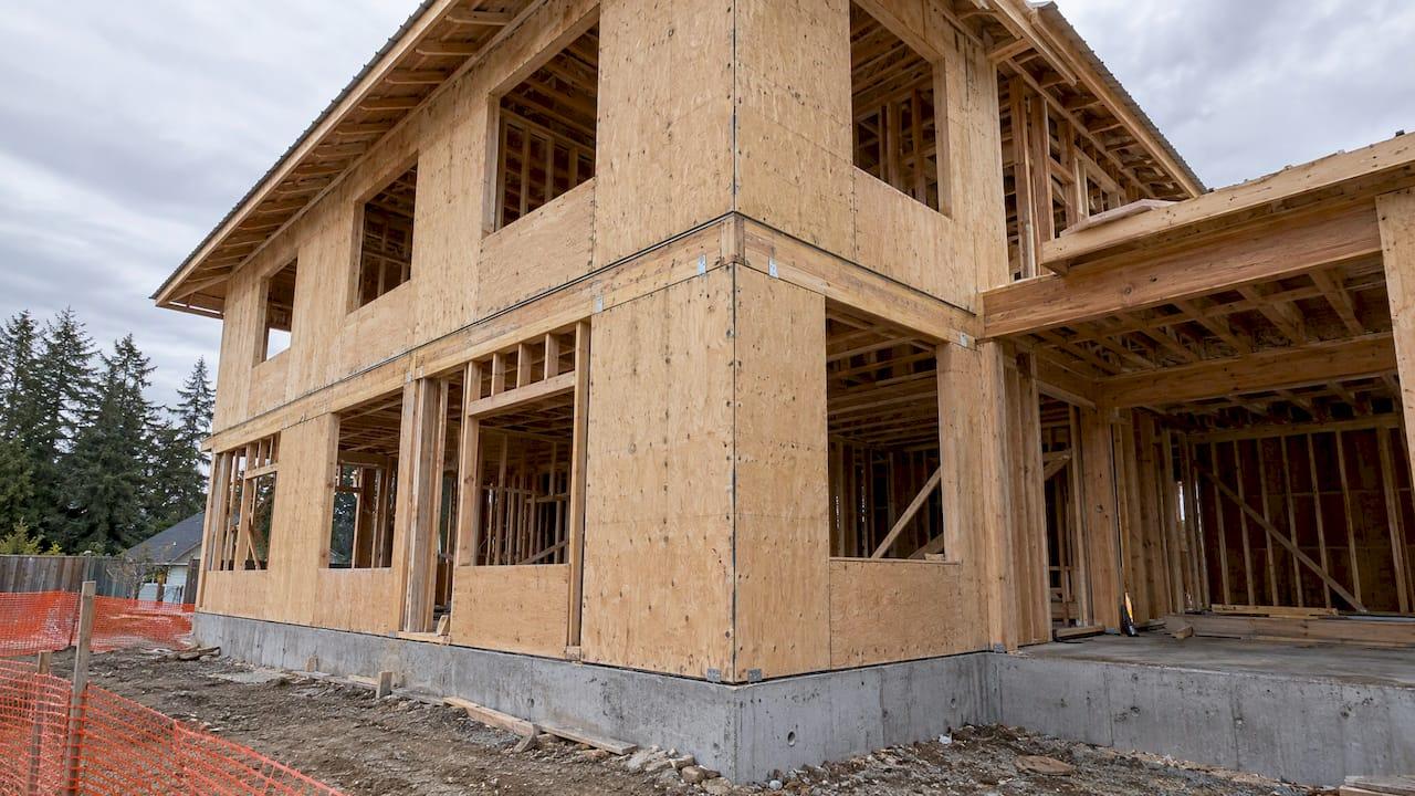
Stacked shear walls are second-story shear wall segments that sit directly over first-story segments of the same length. They give lateral force the simplest path to the foundation. Shear and overturning forces move down through one continuous line of wall, hold-downs and anchorage, with no transfer beam or diaphragm in between. When the walls do not stack, you can still get a load path, but you take on more checks, heavier details and more reviewer questions.
This guide explains how stacked walls work, what to check at each level, what changes when walls are offset or interrupted by openings, and how to organize the calculations so the report holds up in plan review.
TL;DR
- Stacking shear wall segments with the same length from roof to foundation is the simplest load path for in-plane shear and overturning.
- Forces accumulate down the stack: elements that resist forces from more than one story are designed for the sum of the forces from each story.
- Offsets, discontinuous walls and large openings add transfer elements, collectors and extra checks. Find them early by overlaying the floor plans.
- Hold-down type matters. Continuous rod systems accumulate tension from level to level, while post-to-post hold-downs are checked independently at each level.
- Confirm the code edition and local amendments with your building department before you finalize the design.
Table of Contents
- What a stacked shear wall is
- How lateral force travels down a stack
- Connections that make a stack work
- When walls do not stack
- Openings in stacked walls
- Story drift
- California, Oregon and Nevada: verify the adopted code
- Perspective: organize the stack before you size it
- Working through a stack in a calculator
- Try the workflow on your next project
- FAQ
- Sources
What a stacked shear wall is
A shear wall is a vertical element that resists lateral loads from wind or earthquake in the plane of the wall. In a wood-framed building, the floor and roof diaphragms collect those loads and deliver them to the shear walls. A wall stack is the set of shear walls at the same plan location on each level. The top wall passes its load to the wall below, which adds the load from its own level and passes the total further down.
The WoodWorks Hoffmann slides describe the simplest load path for in-plane shear and overturning as shear wall segments that stack on all wood levels and keep the same length. They also note that when first-level walls are missing because the floor plans differ, you need to evaluate alternate systems such as steel braced frames or moment frames.
A continuous (stacked) wall and a discontinuous wall differ in where the force goes:
| Condition | Where the force goes | What you add |
|---|---|---|
| Stacked, same length | Directly into the wall below | Accumulated shear and tension through the stack |
| Stacked, but shorter below | Into a shorter wall with a higher unit shear | Recheck the lower wall's capacity, aspect ratio and hold-downs |
| Offset in plan | Through the floor diaphragm to a different wall | Collectors and diaphragm checks at the transfer |
| No wall below | Into a beam, frame or another system | A separate transfer element, designed for the load it receives |
In a 1- or 2-story wood building, the stack is usually only two walls tall. That keeps the arithmetic manageable, but the connections between the two walls still carry most of the risk.
How lateral force travels down a stack
The load path has four links: the roof or floor diaphragm, the collector or drag strut, the shear wall, and the foundation. The Hoffmann slides say wall stacks collect diaphragm load at each level and accumulate force to the base level, where the bottom wall is anchored to the foundation.
The Applied Technology Council's Briefing Paper 1 states that diaphragms take horizontal forces from the stories at and above them and deliver them to the walls or frames in the story directly below. It also says an upper-story interior shear wall that does not continue to the base must transmit its forces to a floor diaphragm. The same paper describes the foundation as the last link, collecting base shear and passing it into the ground through friction on the lower surface and lateral bearing against the soil.
For a two-story stack, work from the top down:
- Determine the roof diaphragm shear delivered to the upper wall line.
- Design the upper wall: sheathing, nailing, boundary posts and hold-down tension at the second-floor level.
- Add the second-floor diaphragm load to get the total shear in the first-story wall.
- Design the first-story wall for that larger shear and the cumulative overturning.
- Size anchorage and hold-downs at the foundation for the total.
The code states the principle plainly. SDPWS 2015 Section 4.3.6.4.4 requires a load path to the foundation for uplift, shear and compression, and requires elements that resist forces from multiple stories to be designed for the sum of the forces from each story.
Connections that make a stack work
Anchorage at the base
The Hoffmann slides list the base-level needs: sill-plate anchorage for uniform shear and, where required, uplift, plus end hardware such as continuous rods or hold-downs for overturning tension and compression. Check the anchor spacing against the unit shear, not only against a standard schedule.
Boundary elements and end posts
SDPWS 2015 Section 4.3.6.1 requires framing members and blocking in shear walls to be 2-inch nominal or greater. It also requires boundary elements such as end posts to carry the design tension and compression, with end posts framed for full end bearing (SDPWS excerpt on aspect ratios and capacity adjustments). In a stack, the first-story post usually carries the second-story compression plus its own, so the post size or grade often steps up at the lower level.
The SEAU Wood Shear Walls presentation adds a detailing point for higher-capacity walls: certain configurations with 10d nails at 3 inches on center or less call for 3x blocking or two 2x blocking.
Hold-downs: independent or accumulated
The hold-down system changes how you calculate. A Strong-Tie design example explains that continuous rod systems require you to determine and accumulate the incremental tension from the unit shear at each level, while traditional post-to-post hold-downs are calculated independently at each level. Decide which system you are using before you run the numbers, because the tension at the foundation differs in how it is built up. Our guide to hold-down rods in multi-story wood buildings walks through the rod side of that choice.
For taller panels, prefabricated options exist. Simpson Strong-Tie describes its Steel Strong-Wall stacked wall as a prefabricated steel panel for two-story stacked applications on concrete foundations, with compression transferred by nut and rod to reduce wood crushing, and the same anchor bolt templates as the single-story version.

Coordination with everything else in the wall
Detailing often controls the layout. The Hoffhine slides in the same WoodWorks deck note that plumbing stacks are commonly located at wall ends, which collides with hold-downs and threaded rods. Hardware has to be coordinated with finishes, MEP routing and the jamb framing of adjacent windows and doors. Raise this at the framing-plan stage, not at the field walk.
When walls do not stack
Real plans rarely stack perfectly. A garage opening below a bedroom, a great room with a tall wall, or a shifted bearing line all break the stack. The WoodWorks Malone presentation on common challenges recommends overlaying shear walls from floor to floor to see whether they stack or are discontinuous, and to look for irregularities such as offset walls, diaphragms and discontinuous chords.
Offsets
SDPWS 2015 Section 4.3.5.1 says that where out-of-plane offsets occur, the wall portions on each side of the offset are treated as separate shear walls, and collectors must be provided to transfer shear to the individual full-height segments. Each side then needs its own capacity check.
For light-frame residential work, the Penn State paper by Solnosky and Parfitt notes that under the WFCM a line of shear walls cannot shift in plan more than 4 feet, and walls must stack unless the WFCM exception in Section 2.1.3.3d is met, which depends on proper detailing and a continuous load path. That is a prescriptive-method limit. An engineered design follows SDPWS and your adopted code instead.
Discontinuous walls
When an upper wall has no wall below, the force has to go through the floor diaphragm into a transfer element. The SEAU presentation notes that non-stacking walls require the use of Ωo for the beam or transfer slab design. Treat this as a seismic design-category question and confirm the requirement against your adopted ASCE 7 edition.
Top plates and collectors
When top plates serve as chords or collectors, gaps in them break the load path. The WoodWorks article on splicing shear wall top plates at discontinuities says splices must be designed and detailed to carry the load around the discontinuity under SDPWS Section 4.1.4. Per the Landry and Cagle presentation, SDPWS 4.1.9 requires boundary elements to carry design tension and compression, and sheathing cannot be used to splice boundary elements.
Openings in stacked walls
Openings reduce the length of full-height sheathed wall available to resist shear. The Solnosky paper describes three approaches:
- Segmented: full-height, fully sheathed segments that work independently.
- Perforated: walls with framed openings that rely on continuous elements above and below openings to act as a single unit.
- Force transfer around openings: the load is carried around the opening by designed straps and framing.
In a stack, the choice at the lower level often drives the upper one. If the first-story wall is segmented with narrow piers, the second-story segments above them inherit the geometry, and you must decide whether they truly align. Our articles on full-height shear wall segment design and narrow shear wall design cover those segment decisions in detail.
Aspect ratio and capacity adjustments
Narrow piers lose capacity quickly. The Strasser presentation explains that the SDPWS equal deflection method requires shear distribution that gives each wall in a line the same calculated deflection. The simplified method allows distribution in proportion to shear strength, provided walls with an aspect ratio greater than 2:1 have their strength adjusted by the 2bs/h factor. See our pages on the aspect ratio ceiling and 2:1 adjustment and the shear wall ratio for the working rules.
The same principle applies to stacks. Check that a tall upper segment and a shorter lower segment each meet their limits independently.
Story drift
Stacked walls can pass the strength checks and still fail on deflection. The WoodWorks article on multiple shear walls in a line states that deflection comes from the three-term equation in SDPWS Section 4.3.4.1: bending of the end posts, panel shear deformation with nail slip, and bending and deformation of the wall anchorage. Hold-down slip and anchor stretch can dominate on tall walls, which is another reason to settle the hardware early. Story drift is then compared with the limit in your adopted code.
California, Oregon and Nevada: verify the adopted code
Many of our readers work in California, Oregon and Nevada, including Bakersfield. These states adopt model codes on their own schedules and add amendments, and cities and counties add more. The edition of the IBC, SDPWS and ASCE 7 that governs your project depends on the jurisdiction and permit date. Before you start a stacked layout, check three things with the local building department or its published code pages:
- Which code edition applies to your permit application date.
- Whether local amendments change shear wall, hold-down or drift provisions.
- Whether the department expects a specific calculation format or sheet-note standard.
Seismic design category drives much of the work in California, so offset and discontinuity checks tend to matter there. Wind can govern in some Nevada and Oregon locations. Run both and let the controlling case set the design.
Perspective: organize the stack before you size it
We see the same pattern in stacked wood shear wall work. The engineering is rarely the problem. The bookkeeping is.
Wall lines, openings, full-height segments, hold-down forces, transfer straps and roof information all have to line up from story to story. A segment that changes length between floors, or a hold-down that is sized on one sheet and drawn on another, is what slows a plan check.
That is why we built ShearWise Pro around 1-story and 2-story wood buildings instead of a general-purpose structural package. Our approach is to keep each wall line, its openings and its forces in one place, check story drift in the same workflow, and generate a clean PDF report a reviewer can follow.
The point is to spend your time on judgment, such as whether a wall really stacks, and less on re-entering numbers.
Evalin
Working through a stack in a calculator
A consistent routine keeps the checks complete:
- Overlay the plans. Mark every wall line that stacks, shifts or stops.
- Define wall lines and segments on each story, with openings and full-height segment lengths.
- Enter roof and floor information so diaphragm loads reach the right lines.
- Review unit shear and aspect ratio for each segment, applying the adjustment where it is needed.
- Size hold-downs and transfer straps and carry accumulated tension down the stack.
- Check story drift and revisit sheathing or hardware where it fails.
- Generate the report and read it as the plan checker will.
Our two-story shear wall worked example follows this sequence on a 20-foot wall. For the wider context, see wood framing lateral systems and the lateral system components guide.
Once the stacks are settled, accurate shop drawing production and CAD helps carry the hold-down and anchorage details from the calculation into the sheets the field builds from.
Try the workflow on your next project
ShearWise Pro is an online shear wall calculator and report platform for 1-story and 2-story wood buildings. It organizes wall lines, openings, full-height segments, hold-down forces, transfer straps, roof information and story drift checks, then exports PDF reports for review coordination.

The Three-Report Trial is free and produces three watermarked reports. After that, Professional Monthly is $29 per month and Professional Annual is $250 per year. You can sign up to try ShearWise and run a real stack through it.
FAQ
Do shear walls have to stack in a two-story wood building?
Not always, but stacking is the simplest load path. Under the prescriptive WFCM, a line of walls cannot shift more than 4 feet and walls must stack unless a specific exception is met. Engineered designs can use offsets or transfer elements when they are detailed to carry the load.
What happens to hold-down tension in a two-story stack?
It depends on the system. With continuous rods, you accumulate the tension from each level. With post-to-post hold-downs, you calculate each level independently. In both cases the foundation anchorage must resist the total overturning from the stack.
Can a second-story wall sit over an opening below?
It can, but the wall is then discontinuous and the force must go through the floor diaphragm into a beam, frame or other transfer element designed for the load. Where the SEAU guidance applies, that element is designed with Ωo. Confirm the requirement against the code your jurisdiction has adopted.
Does the same code apply in California, Oregon and Nevada?
No. Each state, and often each city or county, adopts its own edition and amendments. Confirm the edition and any local amendments with the building department for your project before design.
Sources
- WoodWorks: Detailing and Best Practices of Developing the Lateral Load Path (Hoffmann)
- WoodWorks: Common Challenges in Wood Lateral Systems (Malone)
- ATC Briefing Paper 1: Building Safety and Earthquakes
- ANSI/AWC SDPWS-2015
- SDPWS 2015, Shear Wall Aspect Ratios and Capacity Adjustments
- SEAU: Wood Shear Walls
- Strong-Tie: Wood Shear Wall Design Example
- Simpson Strong-Tie: Steel Strong-Wall Stacked Wall
- Solnosky and Parfitt: Shear Wall Design in Residential Construction
- WoodWorks: Splicing Shear Wall Top Plates at Wall Discontinuities
- WoodWorks: Practical Considerations for Lateral Analysis (Landry and Cagle)
- WoodWorks: Shearwalls and Diaphragms (Strasser)
- WoodWorks: Calculating the Capacity of Multiple Shear Walls in a Line