
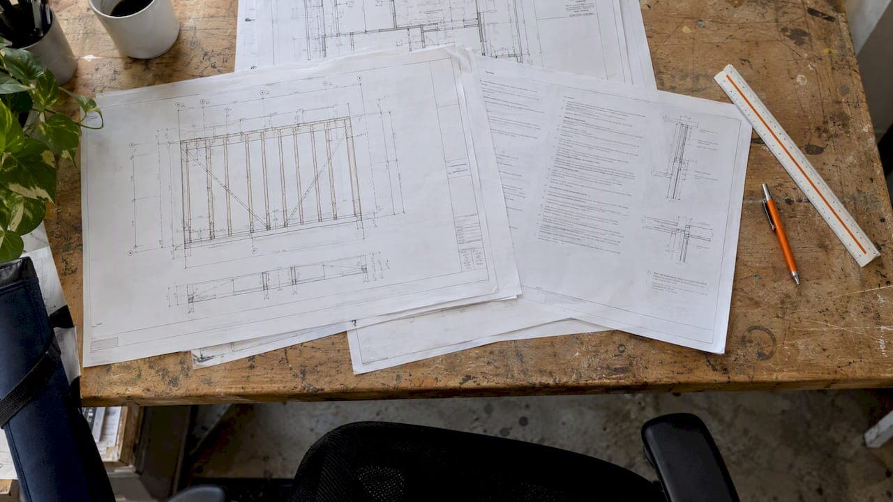
Include on your general shear wall note: the code basis and design method (SDPWS, ASD or LRFD), sheathing and fastening schedule, hold-down and anchor specifications, diaphragm to shear wall load path, a reference to the sealed calculation package, and a statement that field substitutions require engineer approval before installation.
TL;DR:
- Specify sheathing type and thickness, nail size and spacing, panel orientation, blocking, and staggered joints; high framing moisture can cut allowable shear capacity in half.
- Name the opening method, segmented, perforated, or force transfer around openings, because each requires different detailing and can produce widely different predicted internal forces.
- Require contractor anchor location submittals before framing, and state embedment, edge distance, and cast in place tolerances to catch misalignment before walls rise.
- For each wall tag, list design shear, panel length, fastening, hold down capacity, and calculation page; substitutions require revised calculations and a new seal.
- Use engineered shear walls when IRC prescriptive bracing limits for height, spacing, or application are exceeded; those walls need calculated shear, uplift, and drift demands.
Table of Contents
- 1. Standard drawing notes to include: code refs, scope, and general requirements
- 2. Sheathing and nailing schedule notes designers rely on for consistency
- 3. Anchorage and hold-down notes that match capacity to the design load
- 4. Openings and method notes: segmented, perforated, and FTAO
- 5. Diaphragm to shear wall coordination notes
- 6. Shear wall schedule and tag conventions for drawings
- 7. What to attach or reference: calculation package items
- 8. Two drawing-ready example callouts you can paste into project notes
- 9. Author's reviewer note: common pitfalls and drafting tips
- Produce the calculation package your notes reference
- FAQ
- Sources
- Authoritative codes, technical notes, and worked examples to consult
1. Standard drawing notes to include: code refs, scope, and general requirements
A drawing note that cites the wrong code edition or leaves the design method ambiguous sends reviewers straight back to the designer with comments. State the basis up front and remove the guesswork.
We recommend wording close to: "Shear wall design per AWC SDPWS 2021, ASD method, unless noted otherwise. See attached calculations for nominal unit shear capacities and adjustment factors." Note the errata date if your jurisdiction has adopted revisions separately from the base document, since footnote and table changes affect adjustment factors.
Drawings also need to state where prescriptive bracing stops and engineered shear walls begin. IRC Chapter 6 braced wall panels are limited in height, spacing, and application, while engineered shear walls under IBC and SDPWS carry calculated shear, uplift, and drift demands. A short clarifying line avoids confusion during permit review, something we cover in more detail in our comparison of IRC bracing methods and engineered shear walls.
Useful note phrases to keep on hand:
- "Shear walls per schedule are engineered per SDPWS; prescriptive braced wall panels per IRC do not apply at these locations."
- "Design per SDPWS Table 4.3A; adjustments per Section 4.1.4."
- "ASD design values shown; LRFD values available in attached calculations if required by jurisdiction."
2. Sheathing and nailing schedule notes designers rely on for consistency
Nominal unit shear values only hold up if the sheathing and nailing actually installed match what the calculation assumed. The note has to specify material, thickness, nail size, spacing, and orientation clearly enough that a framer in the field and a reviewer at a desk read the same thing.
Typical note content includes:
- Sheathing type and thickness (example: 15/32" APA-rated structural I, one or two sides).
- Edge nailing spacing (example: 8d common @ 4" o.c. at panel edges).
- Field nailing spacing (example: 8d common @ 12" o.c. in the field).
- Panel orientation and blocking requirement where unblocked capacities are not sufficient.
- A note requiring staggered or offset joints on double-sided sheathing to avoid lining up seams on both faces.
Nominal unit shear values come from the SDPWS tables, and those tables carry their own strings attached. Framing moisture content matters more than many drawing sets acknowledge.
Statistic Callout: Per SDPWS 2021, the allowable shear capacity (Ga) is significantly reduced when framing moisture content is high at the time of fabrication. That single footnote can cut a wall's capacity in half, so a note addressing moisture conditions at the time of sheathing installation belongs on every drawing set that doesn't assume ideal lumber conditions. For more on sheathing selection and performance tradeoffs, see our guide to engineered wood shear panel types.
3. Anchorage and hold-down notes that match capacity to the design load
Hold-downs and anchors are where mismatches between drawings and field conditions cause the most rework. The note needs to state the required capacity, not just a product name, so substitutions get evaluated against the actual demand rather than assumed equivalent.
Core note language should require:
- Hold-down capacity equal to or greater than the design uplift shown in the calculation package, with no substitution without engineer approval.
- A clear callout of whether the connection is a cast-in-place strap or a post-installed anchor, since the two carry different placement tolerances.
- Minimum embedment and edge distance values stated directly on the schedule or in the general notes, not left to the installer to infer.
Simpson Strong-Tie's technical notes on hold-downs and tension ties point out that cast-in-place straps are economical but demand precise placement during the concrete pour, while post-installed anchors trade a small cost premium for the ability to adjust location after framing is underway. On projects where cast-in-place accuracy is a known risk, specifying post-installed anchors in the general note can prevent a change order later. Our anchor bolt layout guide walks through typical embedment and spacing values in more depth.
Pro Tip: Require contractor submittal of anchor bolt set locations before framing begins, so misaligned cast-in-place anchors get caught before walls go up instead of during the hold-down install.

4. Openings and method notes: segmented, perforated, and FTAO
How a drawing treats wall openings depends entirely on which design method the calculation used, and the note has to say which one so the field crew and the reviewer are working from the same assumption. APA testing on shear walls with openings found that predicted internal forces can vary widely depending on whether the wall is analyzed as segmented, perforated, or force transfer around openings, which makes the note's method callout a load-bearing piece of information, not a formality.
- Segmented method: use when full-height sheathed segments exist between openings; note "hold-downs required at each full-height segment per schedule; segment aspect ratios per SDPWS." See our segmented shear wall calculation guide for a worked example.
- Perforated method: use when sheathing continues across the wall line with openings included; note "sheathing to extend full height at all pier locations; opening area factored per SDPWS perforated shear wall provisions." A full walkthrough is in our perforated shear wall worked example.
- Force transfer around openings (FTAO): use when calculations rely on strap reinforcement around specific openings; note "sheathing to wrap window and door openings per detail; straps per schedule, see calculation page [X]."
5. Diaphragm to shear wall coordination notes
A shear wall is only as useful as the load path that feeds it, and that path has to be shown, not assumed. Reviewers look for an explicit statement of how diaphragm shear reaches the wall line through collectors and clips.
- Require collectors at each shear wall line end, whether that's a continuous top plate, a dropped beam, or a rim board acting as collector, and state the collector capacity on the drawing.
- Call out shear clip spacing directly: "shear clips @ 16" o.c. at diaphragm to wall connection unless otherwise shown," a spacing commonly referenced in WoodWorks practical shear wall detailing guidance.
- Reference the specific calculation page for collector forces so reviewers can trace the number back to its source.
A short primer on how these elements fit together is in our guide to wood framing lateral systems.
6. Shear wall schedule and tag conventions for drawings
The schedule is the fastest cross-check a reviewer has against the calculation package, so its columns matter as much as the notes themselves.
Minimum columns we recommend:
- Wall tag and wall line reference.
- Panel length and sheathing type and fastening.
- Nominal unit shear used and design shear in plf.
- Hold-down ID and rated capacity.
- Anchor bolt note, story, and calculation reference.
Tag segmented piers individually rather than lumping an entire wall line under one mark, label openings clearly, and add a notes column for field constraints like minimum edge distance. Our full-height shear wall segment guide has more on tagging conventions for segmented walls.
| Column | Purpose |
|---|---|
| Wall tag | Identifies the wall line on plan |
| Panel length | Confirms segment or pier dimension |
| Sheathing/fastening | Ties schedule to nailing note |
| Design shear (plf) | Cross-checks against calculation |
| Hold-down ID/capacity | Confirms uplift connection matches design |
| Calculation ref | Points reviewer to the sealed source page |
7. What to attach or reference: calculation package items
The general notes are only a summary. They need to point to a sealed calculation package that actually backs up every number on the drawing.
That package should show:
- Nominal unit shear selection with the SDPWS table and edition or errata date noted.
- Adjustment factors applied, including moisture and specific gravity where relevant.
- Hold-down forces, anchor verification, and story drift checks for multi-story walls.
State plainly on the drawing that any field substitution requires a resubmittal with revised calculations and a new seal, not a verbal approval on site.
8. Two drawing-ready example callouts you can paste into project notes
Having a template on hand saves time on repetitive note writing across similar projects.
- Example A, single-story fully sheathed exterior wall: "15/32" structural I sheathing, one side, 8d common @ 4" o.c. edge / 12" o.c. field. Hold-down per schedule at each end of full-height segment. Anchor bolts per schedule. See calculation sheet S-3 for design values."
- Example B, two-story wall with FTAO at window openings: "Sheathing wraps window openings per detail 5/S-4. Straps per schedule at header and sill, blocking as shown. Hold-downs at wall ends per schedule. See calculation sheet S-6 for FTAO force derivation."
Place both snippets on the general structural notes sheet, with the schedule carrying a short reference back to the specific calculation page for each tagged wall.
9. Author's reviewer note: common pitfalls and drafting tips
The biggest recurring problem we see in review isn't bad engineering, it's an implied load path instead of a drawn one. Straps around openings get left off the framing plan even when they're in the calculation, and anchor bolt locations drift during the concrete pour more often than drawings account for. Requiring contractor as-built verification of anchor locations, stating a tolerance for cast-in placement, and coordinating architectural openings before the shear wall calculation locks in all save rework later.
— Evalin
Produce the calculation package your notes reference
Every note template above points back to a sealed calculation, and generating that package by hand for every wall line, hold-down, and opening eats hours that most firms would rather spend elsewhere. ShearWise Pro organizes wall lines, openings, full-height segments, hold-down forces, transfer straps, and story drift checks into one workflow, then exports a clean PDF built for exactly this kind of review coordination.

- Organize calculations by wall line and story without rebuilding spreadsheets for every project.
- Export reviewer-friendly PDFs that match the schedule and note conventions covered above.
- Check validation examples in the ShearWise Pro Validation Library to see sample report output.
Start with the Three-Report Trial at no cost, or visit our pricing page for current subscription options for ongoing project work. See plans and get started.
FAQ
What code should shear wall general notes cite?
Cite AWC SDPWS 2021 as the primary design standard, along with the specific table and edition or errata date used. Also state whether the design follows ASD or LRFD, since that affects which capacity values apply.
Can a hold-down be substituted in the field without approval?
No. Hold-down capacity must match the design uplift load shown in the calculation, and Simpson Strong-Tie's technical notes confirm that substitutions can negate the connection's rated capacity. Any change requires engineer review and often a revised, resealed calculation.
How should openings be noted on shear wall drawings?
State which design method the calculation used: segmented, perforated, or force transfer around openings (FTAO), since each requires different detailing around the opening. APA testing found that predicted internal forces vary widely between methods, so the drawing must identify which one applies at each opening.
When is an engineered shear wall required instead of a prescriptive braced wall panel?
Engineered shear walls are required when a project exceeds the height, spacing, or load limits that IRC Chapter 6 sets for prescriptive braced wall panels. Beyond those limits, the design must follow IBC and SDPWS provisions with calculated shear, uplift, and drift values.
What minimum information belongs in a shear wall schedule?
At minimum, include wall tag, panel length, sheathing type and fastening, design shear in plf, hold-down ID and capacity, anchor bolt note, and a calculation reference. These columns let a reviewer cross-check the drawing against the sealed calculation without flipping through the full report.
Sources
- AWC Special Design Provisions for Wind and Seismic (SDPWS) — 2021
- IRC Chapter 6 — Wall construction (braced wall panels)
- Practical considerations for shear wall connections and details — WoodWorks (2023)
- APA research on shear walls with openings and FTAO testing
Authoritative codes, technical notes, and worked examples to consult
- AWC Special Design Provisions for Wind and Seismic (SDPWS) — 2021
- IRC Chapter 6 — Wall construction (braced wall panels)
- Practical considerations for shear wall connections and details — WoodWorks (2023)
- APA research on shear walls with openings and FTAO testing
- Simpson Strong-Tie technical notes for holdowns and tension ties